
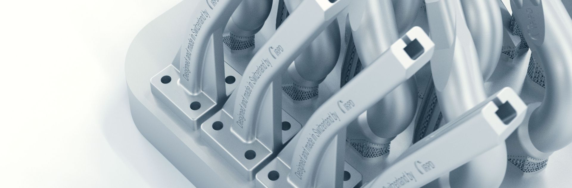

Coolant supply and nozzle design
Every grinding process generates a significant amount of heat. The correct application of coolant is pivotal in cooling the workpiece, safeguarding it against thermal damage, thus playing an essential role in the overall grinding process. Please read this Motion Blog to understand why 3D-printed nozzles enhance the efficiency of coolant application and learn about the advantages of equal velocity coolant delivery.
Design of the coolant nozzles
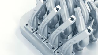
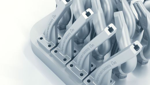
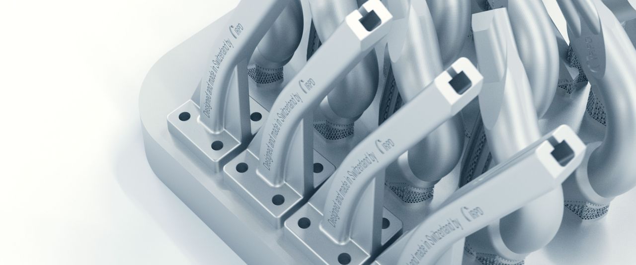
Coolant nozzles are crucial for delivering cooling to the grinding zone and performing key functions such as cleaning, lubricating, and cooling. In toolmaking, where workpieces often vary and are produced in small batches, the ability to flexibly adjust the position of nozzles is vital. Nozzles, made up of modular plastic elements, have gained popularity for their ease of manual positioning and quick adaptability to new workpiece geometries. However, these nozzles face a drawback: the plastic sections at the openings are prone to damage, leading to turbulence and diminished cooling efficiency. Alternatives that employ stainless steel metal segments present an improvement by enhancing durability. Yet, they, too, due to their focus on flexibility, affect the nozzle system's overall efficiency. For both nozzle types, each joint in the system introduces turbulence, detracting from the coolant delivery's effectiveness. Furthermore, unintended shifts in the optimal positioning are always a risk, thus potentially undermining the cooling process.
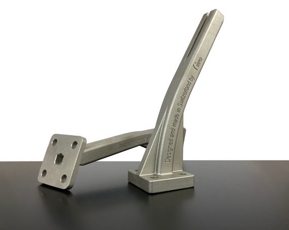
Owing to these drawbacks, experts frequently opt for solid steel nozzles in high-performance grinding applications, ensuring a consistent and accurate coolant supply. Innovations in additive 3D manufacturing, including selective laser melting (SLM) and laser powder bed fusion (LPBF), are paving the way for the creating of novel forms of stainless steel nozzles. Leveraging complex flow simulations, these advanced manufacturing processes facilitate the design of coolant nozzles with optimal flow profiles, which are unattainable through traditional production techniques. The goal is to generate smooth, vortex-free, coherent coolant jets, maximizing the efficiency of the coolant delivery.
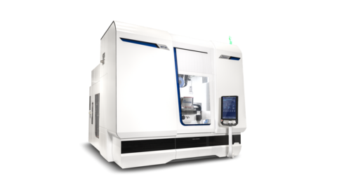
A 3D-printed nozzle optimized for flow exhibits lower resistance at the same flow rate than a standard nozzle. These nozzles have their own numerical control (NC) axis in certain applications. This feature accounts for the gradual reduction in grinding wheel size due to dressing, ensuring the nozzle remains in the optimal position. An example of this principle in action is integrated on the MÄGERLE MFP 50 or MFP 100.
Advantages of "equal velocity" coolant delivery
The fundamental principle involves matching the coolant jet's speed with the peripheral speed of the grinding wheel, a method referred to as "equal coolant velocity." This approach was pioneered in the 1980s by H.W. Ott in Switzerland. Subsequent research by Prof. Karpuschewski at the IWT of the University of Bremen in 2022 corroborated Ott's theories. This research, focusing on gear profile grinding, confirmed that synchronizing the coolant's speed with the grinding wheel maximizes the specific chip volume V'w. The specific chip volume indicates the amount of material that can be removed before necessitating the dressing of the grinding wheel due to either profile loss or the onset of grinding burn. Interestingly, the findings suggested that delivering coolant at a speed lower than that of the grinding wheel’s surface speed is more efficient than a higher speed of the coolant jet than the peripheral speed of the grinding wheel.
Influence of the jet velocity on the specific chip removal volume

Wheel surface speed: 35m/s
Q-prime: 7.5 to 25 mm3/mm/sec
Source: Prof. Dr. Karpuschewski, IWT Bremen
Equal coolant velocity delivery in practice
While it is possible to calculate jet speeds, this approach is not practical for workshop applications. To practically achieve equal velocity in coolant delivery, the grinding nozzle should be positioned above the center line of the grinding wheel. The coolant jet is best directed to tangentially strike the circumference of the grinding wheel at a 20-degree angle.
Equal velocity coolant je delivery according to Ott (Vk = Vc)

Coolant nozzle set at 20° angle;
Coolant jet hits grinding wheel's periphery tangentially;
Coolant jet "sticks" to grinding wheel
When the coolant jet's speed is synchronized with the grinding wheel's peripheral speed, the coolant adheres to the grinding wheel, ensuring efficient coolant transport into the grinding zone. This alignment between the coolant supply and process parameters is critical in demanding grinding applications in ball-bearing manufacturing and automotive production industries. In toolmaking, however, practices might deviate from this ideal setup. Nonetheless, satisfactory results can still be achieved by correctly adjusting the nozzle positions. Subsequently, a valve on the machine's coolant feed pipe can be used to regulate the coolant flow rate. Before supplying coolant, however, the workpiece must be distanced from the grinding wheel, the nozzle positioned as described, and the grinding wheel brought up to operating speed. Next, the coolant valve is gradually opened until the coolant jet firmly adheres to the grinding wheel, ensuring that the coolant effectively flows through the grinding zone when the grinding wheel contacts the workpiece.
Position of the coolant nozzle for cylindrical grinding


The approach to positioning the nozzle, initially described for cylindrical grinding, is equally applicable to surface grinding. Begin by separating the grinding wheel from the workpiece. Next, adjust the nozzle to the specified position and accelerate the grinding wheel to its operating speed. Subsequently, gradually open the coolant valve until the coolant jet firmly adheres to the grinding wheel.
Position of the coolant nozzle for surface grinding


Summary
An overview of the most important points in the KSS nozzle arrangement:
- Equal coolant delivery velocity vk = vc
- Tangential impact of the coolant jet on the grinding wheel circumference
- Nozzle position with sufficient distance and correct angle of impact (20°)
- Volume flow between 1.5 and 5 liters per minute per mm grinding wheel width
Can we help you?
Are you interested in 3D-printed coolant nozzles from IRPD? Or do you need support with the optimum design of your coolant delivery system? Please get in touch with us. Our experts are happy to help.
Literature
[1] H.W. Ott & Co., Fundamentals of Grinding Technology, 1986, self-published
[2] Prof. Dr. habil. Bernhard Karpuschewski, Demand-oriented cooling lubricant supply, IWT Bremen, 2024 Schleiftagung Fellbach