Rotary Dressing Tools, Part 2: Diamond Dressing Rolls
In profile grinding, the shape and accuracy of profiles are directly determined by the geometry of the dressed grinding wheels. In the 1960s, rotating diamond dressing rolls were developed to maintain the precision of grinding wheels and workpieces in large-scale production. However, advancements were not limited to rotary dressing rolls alone; they encompassed the entire system, including the machine tool and the dressing unit.
For more information on the different types of diamond dressing rolls and the key parameters for their effective use, please refer to this motion blog.
Reverse and positive electroplated diamond dressing rolls
Profile dressing rolls are divided into two main groups:
- Reverse electroplated diamond rolls: Here, the diamonds are placed in a negative mold that is subsequently destroyed.
- Positive electroplated diamond rolls: In this process, a layer of diamonds is applied directly to a precisely manufactured steel carrier body.
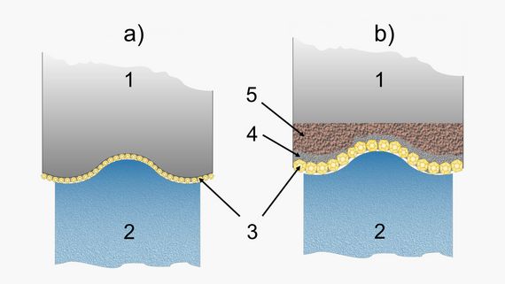
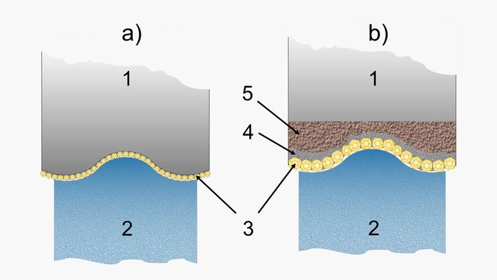
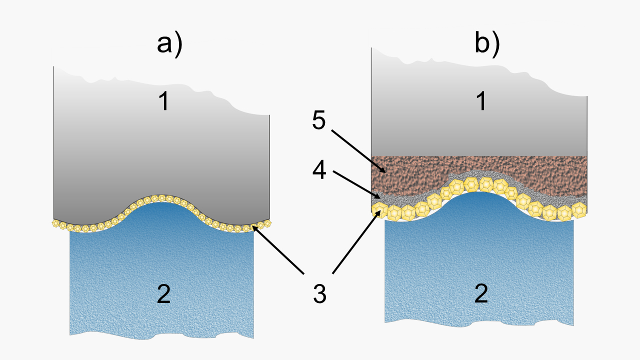
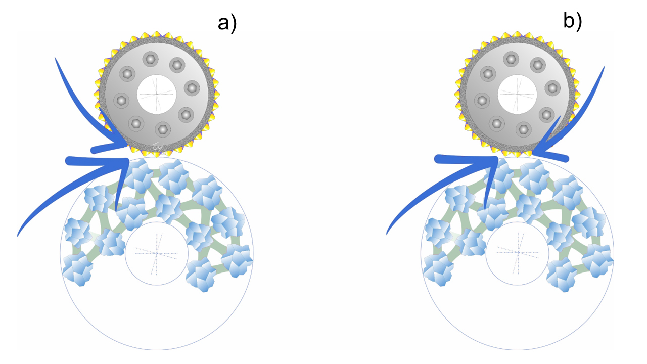
The figure below illustrates the difference between the two processes. On the left is the positive electroplated dressing roll, which consists of a steel body shaped to the final form of the workpiece, with the thickness of the diamond crystal subtracted. On the right is the reverse electroplated dressing roll, featuring a more complex design and larger diamond crystals. This article focuses on reverse-plated diamond rolls, which are better suited for precision work. While positive-plated diamond rolls have their place in prototype manufacturing, they are less suitable for large-scale production.
The more relevant process for high-precision applications is the reverse or negative electroplated process, which in turn can be divided into three sub-processes:
1. Reverse electroplated diamond dressing rolls with a single layer of randomly distributed diamonds
The first step in the process involves creating a precision mold or die, typically made from aluminum, and occasionally from graphite. This mold is machined using a high-precision CNC lathe to produce a profile that, in mirror image, corresponds to the final dimensions and shape of the diamond dressing roll. The turning tool used for this is equipped with a diamond cutting edge, featuring a precisely lapped and measured radius. Once the profile is machined, the mold is coated with a single layer of diamonds, either randomly distributed or hand-set. These diamonds are then electroplated with a thick layer of nickel. A steel sleeve is placed concentrically to the reference diameter of the aluminum mold, and the remaining space between the nickel layer and the steel sleeve is filled with a synthetic resin compound. Finally, the aluminum mold is destroyed as part of the process.
This method produces highly precise dressing rolls because all the diamonds are positioned on the high-precision turned negative mold's outer "plane of rotation". The diamonds are not glued to the inside of the die but are initially held in place by centrifugal force. This process results in a high packing density, enables the creation of very small profile angles and radii, and requires minimal or no lapping for final accuracy. Although these dressing rolls require a significant investment, the cost is justified by their long service life and exceptional precision. Among the types described, the dressing roll with randomly distributed diamond grains is the most accurate dressing tool.
2. Reverse electroplated dressing rolls with hand-set diamonds
In this method, the diamonds are not randomly placed in the negative mold but are instead meticulously set by hand according to a predetermined pattern. Before the electroplating process begins, each diamond crystal is glued into its precise, designated position. This approach allows for the advance determination of packing density, ensuring controlled overlap of diamonds on conical diamond dressing rolls or those used for shoulder grinding. As a result, the grinding wheel is not dressed too finely at any point, significantly reducing the risk of grinding burns. Additionally, critical areas that are prone to faster wear can be reinforced with larger diamonds. Hand-set dressing rolls can also be equipped with edge reinforcements, such as placing CVD rods in areas of the dressing roll that are more susceptible to wear.
3. Sintered metal bonding (infiltration process)
These dressing rolls are produced by infiltrating hot, liquid metal into a mold, followed by sintering in a furnace at 800°C. Due to the variations in shape and differences between the largest and smallest diameters, different shrinkage rates can occur, which impacts the overall geometric accuracy. As a result, these dressing rolls require lapping to achieve the necessary precision. Despite this additional step, the metal matrix used in these rolls is highly resistant to wear, giving them the longest service life among the various typed of dressing rolls.
Positive electroplated dressing rolls
Direct or positive electroplated dressing rolls with a single diamond layer differ from reverse-plated dressing rolls in that the diamond endpoints do not all lie precisely on the outer "plane of rotation". The statistical variation in nominal diamond crystal size, along with the resulting differences in actual crystal size, reduces the accuracy of these dressing rolls. However, they are cost-effective and well-suited for prototypes and applications where lower accuracy and shorter tool life are acceptable.
Application guidelines for the use of diamond dressing rolls
The most important factors influencing the optimization of a dressing operation are
- The direction of rotation between the grinding wheel and diamond roll
- Speed ratio qd between the grinding wheel and the diamond roll
- Infeed of the diamond dressing roll in mm/min or mm per wheel rotation
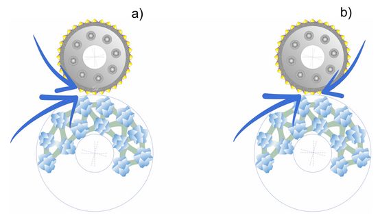
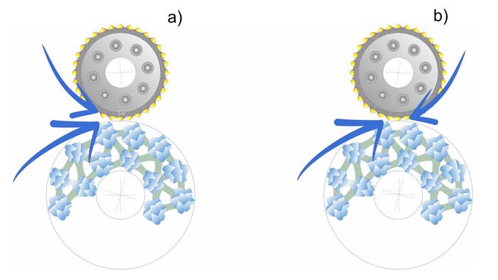
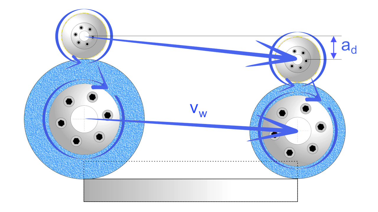
The direction of rotation of the diamond dressing roll relative to the grinding wheel, along with the speed ratio qd between the grinding wheel and the rotating diamond dresser, significantly influences both the stock removal rate and the resulting surface quality of the workpiece. The directions of rotation are categorized as synchronous and asynchronous dressing. In synchronous dressing, the grinding wheel and the diamond dressing roll move in the same direction at the point of contact. In asynchronous dressing, the grinding wheel and the dressing roll move in opposite directions at the point of contact.
The relative speed qd of the grinding wheel and the dressing wheel in relation to each other influences the grinding wheel's topography or its surface roughness.
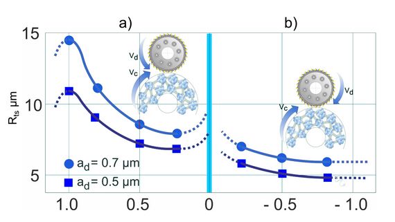
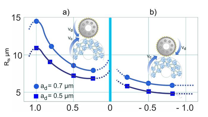
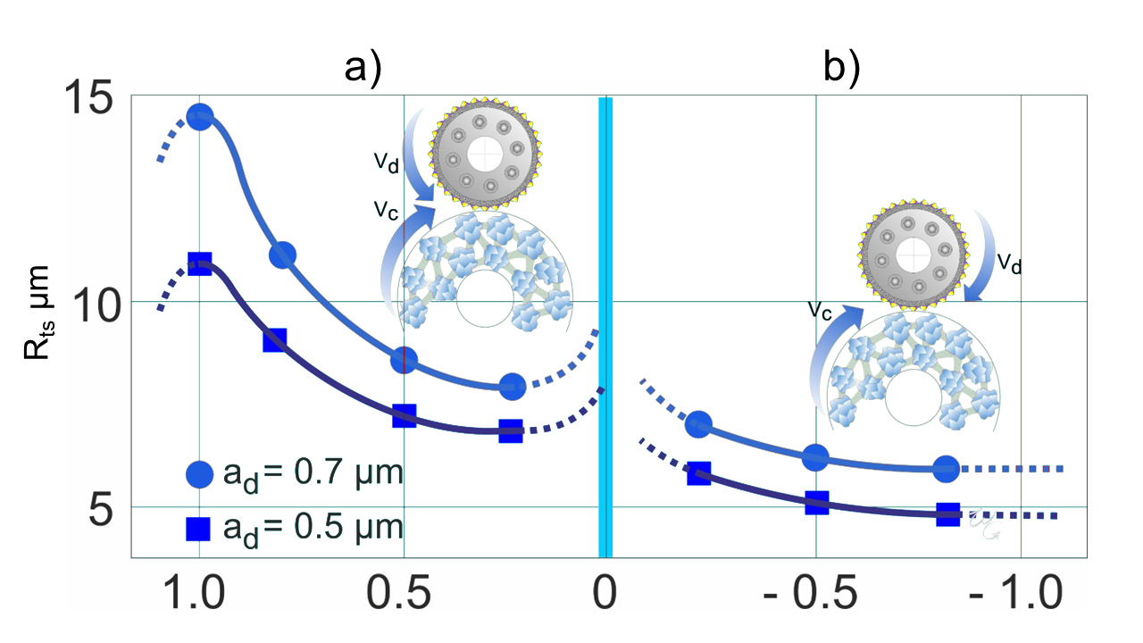
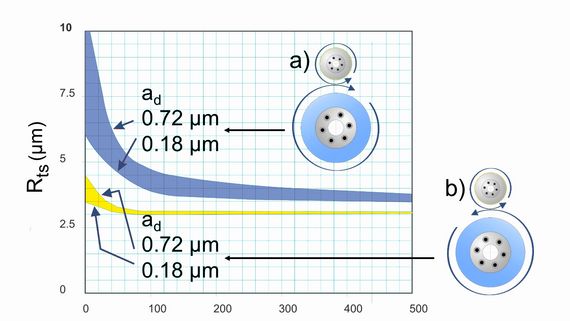
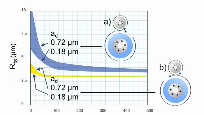
The diagram illustrates that the speed ratio qd between the diamond roll and the grinding wheel has a significant impact on the surface roughness Rts of the grinding wheel. In synchronous dressing, where the grinding wheel and diamond roll rotate in the same direction at the point of contact, the surface roughness Rts is coarser and more aggressive compared to asynchronous dressing, where the two rotate in opposite directions. This effect is consistent across different dressing depths ad (the penetration depth of the dressing roll into the grinding wheel per revolution). As the speed ratio qd approaches 1, the grinding wheel's surface roughness becomes rougher. However, at qd = 1, the diamond roll would be damaged due to a crushing mechanism between the diamonds and the grinding wheel. Therefore, a speed ratio of qd = vR/vc of 0.8 is recommended for synchronous dressing.
The graph also shows that in asynchronous mode, changing the speed ratio qd has only a slight effect on the grinding wheel's surface roughness Rts. Moreover, asynchronous dressing produces a much finer surface roughness than synchronous dressing. Despite this, a higher surface roughness is often desirable during grinding, as it allows the grinding wheel to work cooler and more aggressively, reducing the risk of grinding burns on the workpiece. For this reason, synchronous dressing is generally preferred whenever possible.
The steeper penetration angle of the diamond in synchronous mode explains the coarser resulting wheel surface roughness Rts. Asynchronous dressing should only be considered when the desired surface quality cannot be achieved with synchronous dressing or if the dressing unit's drive is too weak. If the drive unit is inadequate, the grinding wheel might drive the rotating dressing roll, accelerating it to the speed of the grinding wheel.
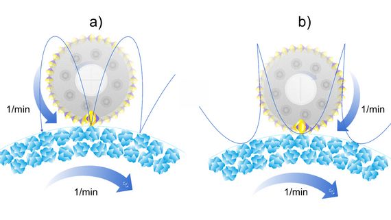
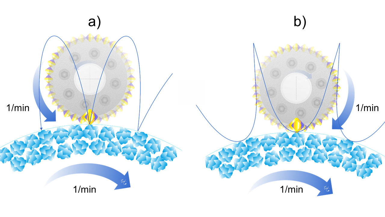
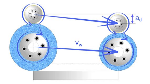
The following diagram depicts both dressing modes and the theoretical dressing path of a single diamond on the periphery of the dressing roll. Although the example uses a single diamond for illustrative purposes, in reality, hundreds to thousands of diamonds are present on the rotating dressing roll. In synchronous dressing, the individual diamond strikes the grinding wheel vertically, resulting in a "hammer blow" that makes the grinding wheel sharper and more aggressive. In contrast, in asynchronous dressing, the contact path of a single diamond creates a "glancing blow" on the grinding wheel's surface, leading to a finer surface finish.
The illustration at the top left depicts the vertical impact of a dressing diamond in synchronous dressing, often referred to as a "hammer blow," on the grinding wheel. In contrast, the illustration on the right shows the "glancing" impact of the diamond crystal in asynchronous mode. Generally, the service life of the diamond roll is longer in synchronous mode compared to asynchronous mode. This difference in service life can be attributed to the distinct impact paths of the individual diamond crystals.
In synchronous dressing, the diamond crystals are only briefly in contact with the grinding wheel. In asynchronous mode, however, the crystals make a sliding contact with the grinding wheel due to the "inverted" hypocycloidal path, remaining in contact for a longer duration. This extended contact leads to greater overlap and, consequently, a higher thermal load on the diamond crystals. The increased overlap also explains why the effective roughness depth Rts is lower in asynchronous mode. To mitigate the thermal load during the dressing process, it is essential to flood the diamond roll with plenty of grinding fluid.
Useful formulas for calculating the dressing parameters
Speed ratio qd: Describes the ratio between the surface speeds of the grinding wheel and the dressing roll.
qd = surfacespeedofdressingroll/ surfacespeedofgrindingwheel
qd= vRvc=(ratio)
Calculation of the surface speed in m/s of the dressing roll and the grinding wheel:
V = (n×d× π)/ (1000 × 60)
Calculation of the revolutions per minute (n) of the dressing roll or grinding wheel based on the surface speed in m/s (V)
n = (V×1000 ×60)/ (d × π)
- V = surface speed in m/s of the grinding wheel or dressing roll
- d = diameter in mm of the grinding wheel or dressing roll
- n = revolutions/min of the grinding wheel or dressing roll
Critical parameters for the use of dressing rolls
Drive unit power
As cylindrical grinding machines are not equipped with such powerful dressing drives as creepfeed grinding machines, it must be ensured that the dressing unit drive has sufficient power.
Infeed depth ad per grinding wheel revolution
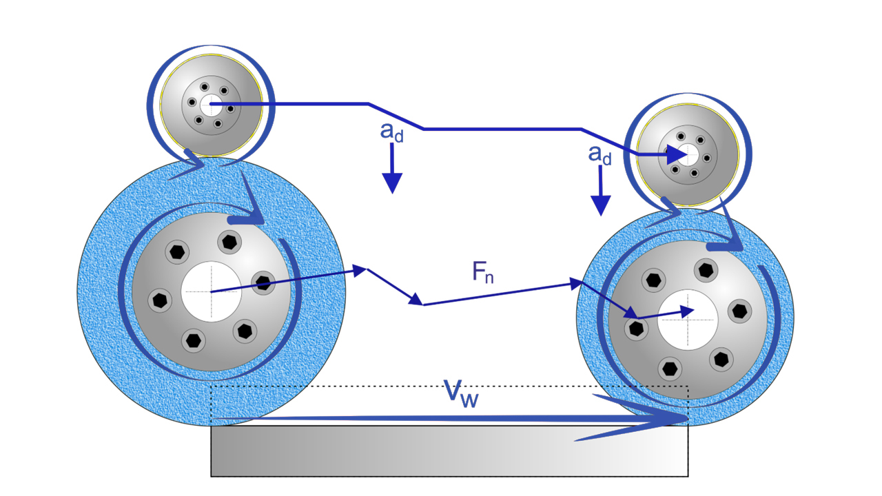
The amount of dressing per grinding wheel revolution directly affects the effective depth Rts of the grinding wheel, i.e., the greater the infeed depth, the greater the effective depth. However, this only applies if the roll-out time is not considered. The infeed depth ad should ideally be between 0.5 µm and 1.5 µm per revolution of the grinding wheel. The maximum infeed depth should not exceed 1.5 µm per revolution of the grinding wheel, as excessive infeed rates reduce the service life of the dressing roll or even damage the dressing roll.
Grinding wheel surface speed (vc ) during dressing
For dressing, the same surface speed of the grinding wheel vc as during grinding should be selected whenever possible. A vitrified bonded grinding wheel is never a completely homogeneous body. The grinding wheel can change unevenly in diameter if dressed at a lower speed than the final operating speed. This expansion, even if slight, would result in an uneven grinding wheel, which could cause profile or surface defects.
Drive unit for diamond roll dressers
The dressing drive unit should always be equipped with an infinitely variable speed drive to adjust the speed ratio qd and the direction of rotation to influence the effective roughness depth Rts of the grinding wheel to be dressed. It is also important that the speed remains constant at varying dressing loads.
Roll-out revolutions for dressing rolls
When a dressing roll is dressing a profile into a grinding wheel, the roll-out revolutions (horizontal axis in the diagram) must be limited as soon as the roller has reached its final dressing depth. If the dressing roll continues to dress in its final position, the effective depth Rts of the grinding wheel becomes too smooth, as shown below. The roughness of the grinding wheel remains high at low roll-out revolutions in both synchronous and asynchronous modes. At fifty roll-out revolutions, the surface roughness Rts decreases in both dressing modes. This low roughness can result in the wheel not being free-cutting, which can lead to profile errors due to high grinding pressure and grinding burns.
CD dressing for creepfeed grinding
Grinding with continuous dressing (CD dressing) achieves the highest stock removal rates, as the grinding wheel remains continuously sharp and free-cutting. However, the high removal rate comes at a price, reflected in the high wheel consumption. To illustrate this high wheel consumption, let us assume a diamond wheel infeed of 0.5 µm per revolution of the grinding wheel at an average wheel RPM of 1,640 and a constant surface speed vc of 28 m/s:
| 400 mm new wheel diameter: | vc = 28 m/s constant | rpm = 1337 |
| 275 mm final stub wheel diameter: | vc = 28 m/s constant | rpm = 1945 |
At an average speed of 1640 RPM, the amount of dressing per minute in CD mode is calculated as follows: 1640 x 0.0005 x 2 = 1.65 mm wear on the wheel diameter in one (1) minute. A 400 mm grinding wheel with a stub diameter of 275 mm would be used up in about 75 minutes! For this reason, the infeed quantity should be as small as possible to improve the process's efficiency.
Machine tool manufacturers have developed "in-process dressing," or IPD for short, to counteract the high grinding wheel consumption. IPD is similar to CD dressing and places the same demands on the machine tool. In contrast to CD dressing, the dressing roller in IPD does not dress continuously but only periodically when the grinding wheel becomes too blunt, and the normal forces rise above a certain preset level. The advantages are lower wheel consumption, reduced chips, and grinding wheel abrasion.
Conclusion
Diamond dressing rolls offer the user high efficiency and constant precision in high-volume production. They can be used on all modern deep and cylindrical grinding machines from the UNITED GRINDING Group.


