


연삭해야 할 다양한 부품이 많고 이를 위해 빈번하게 장치를 교체해야 하는 경우, 시간 낭비를 최소화하는 것이 얼마나 중요한지 알고 있습니다. 이 때 STUDER의 액티브 포지셔닝 프로브는 다음과 같이 다양한 기능을 수행합니다.
- 기본 설정 또는 B축 회전점에 대한 프로브 및 연삭 휠을 기준으로 측정
- 설정 모드에서 수동으로 공작물 교체
- 길이 방향 위치 지정
- 나사산 위치 지정
- 원주 위치 지정
- Ø 및 길이 점검
- 기준 치수 Z를 이용한 자동 감지
마지막 포인트인 STUDER 기계에서 원통 연삭 시 새로운 공작물을 자동으로 감지하는 것에 대해 아래에서 좀 더 자세히 살펴보겠습니다.
기준 치수 Z를 이용한 자동 감지
기준 치수 Z는 설정 시 한 번만 설정됩니다. 테이블 위의 스케일에서 프로브까지의 기준이 설정됩니다. 간단히 말해, 프로브가 어느 길이에서 회전하여 공작물을 찾아야 하는지 기계에 알려줍니다. 이 기준이 한 번 생성되면 나중에 프로그램에서 새 공작물의 새로운 길이 값과 Ø 위치를 정의할 수 있습니다. 이를 통해 프로브가 올바른 위치로 회전하고 설정 모드에서 새로 감지할 필요 없이 새 공작물의 영점을 찾습니다. 이 때 기계에 Quick-Set 옵션이 장착되어 있어야 합니다.
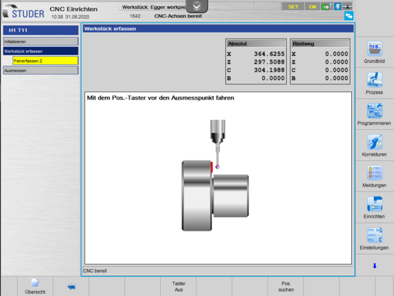

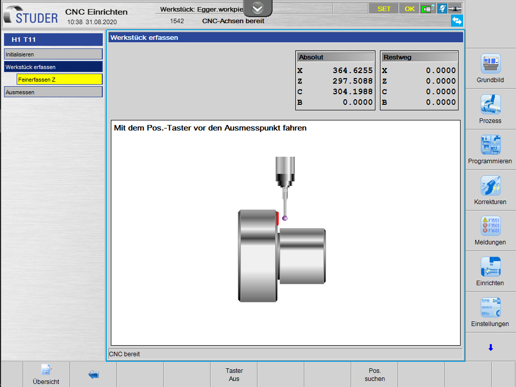
설정 절차는 완전히 일반적으로 수행됩니다.


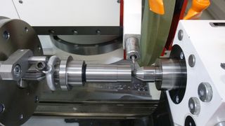
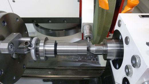
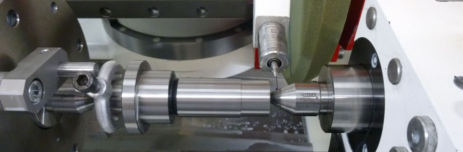
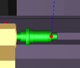
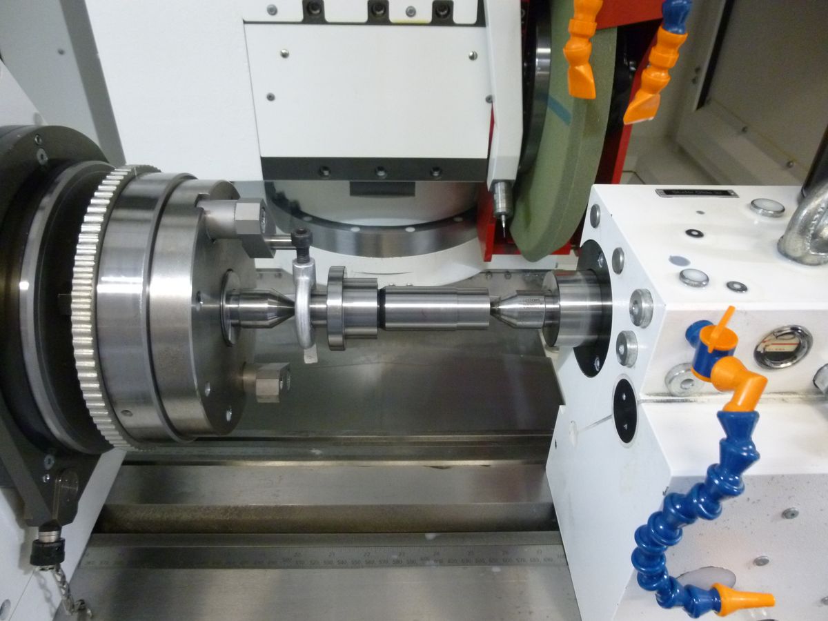
버튼을 사용하여 수동으로 프로빙할 칼라 앞 약 10mm로 이동하십시오. 볼이 프로브 샤프트가 아닌 칼라에 닿도록 유의하십시오(언더컷, 칼라 높이).
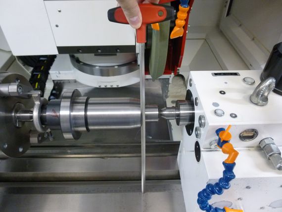
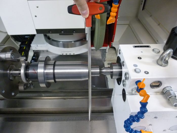

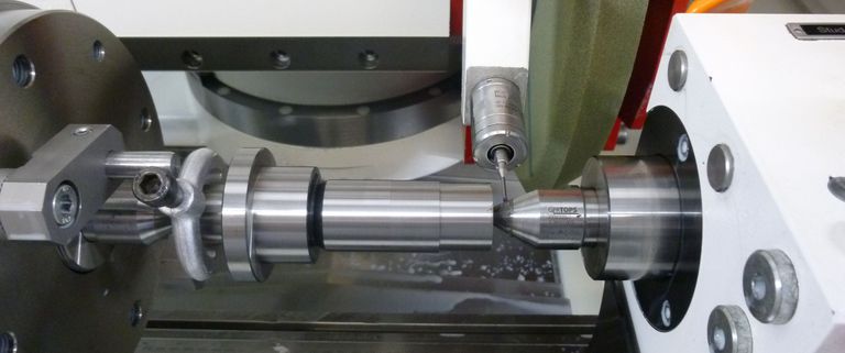
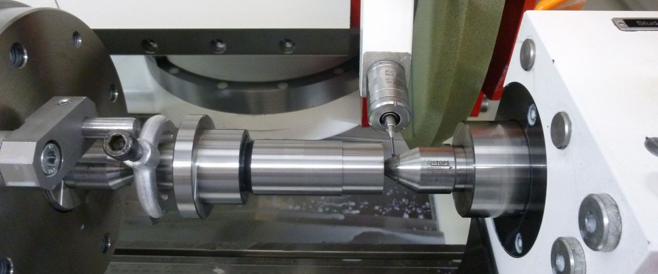
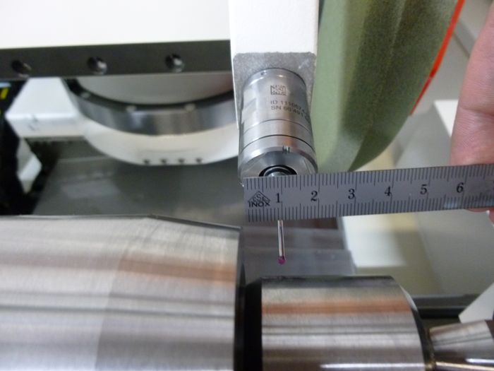
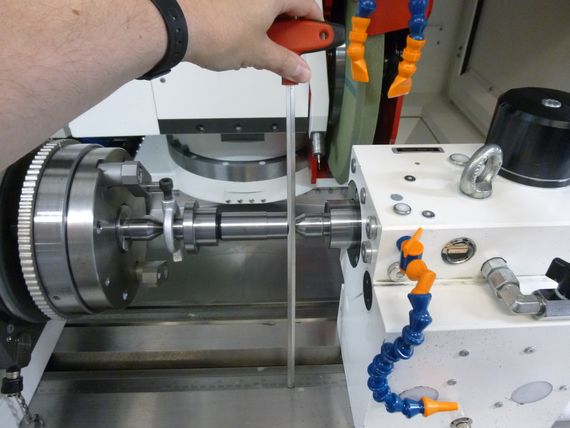
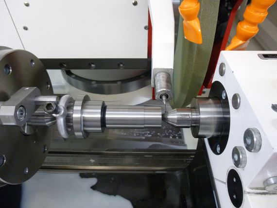
이제 프로브 위치에서 테이블 스케일까지 수직이 되는 위치를 찾습니다. 이 예시에서는 긴 도구를 사용하여 이 작업을 수행합니다. 그러나 더 큰 브래킷 또는 직각추를 사용할 수도 있습니다.
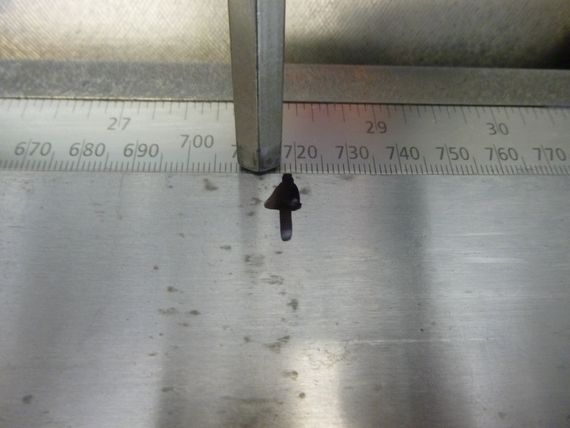

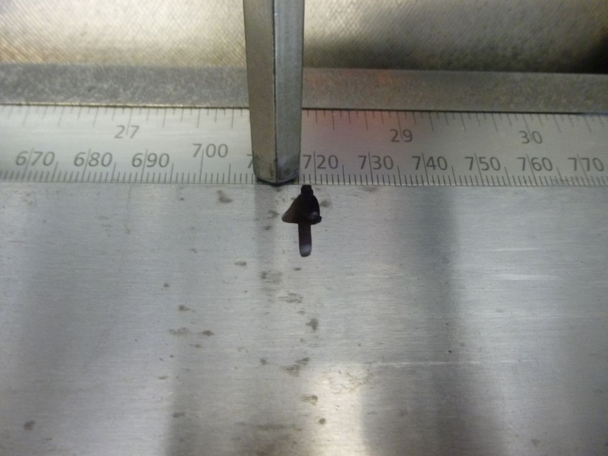
이 예시에서는 718mm를 읽어냅니다.


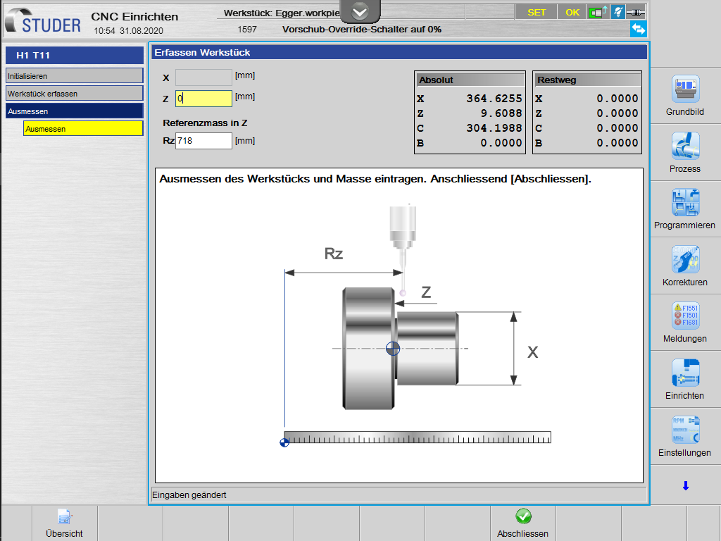
이 718mm는 이제 Rz 필드에 입력됩니다. 또한 Z 필드에 0(영)을 입력해야 합니다. 따라서 첫 번째 감지는 공작물 영점에서 정확하게 수행해야 합니다.
이제 공작물 영점과 기준 치수 Z가 설정되었습니다.
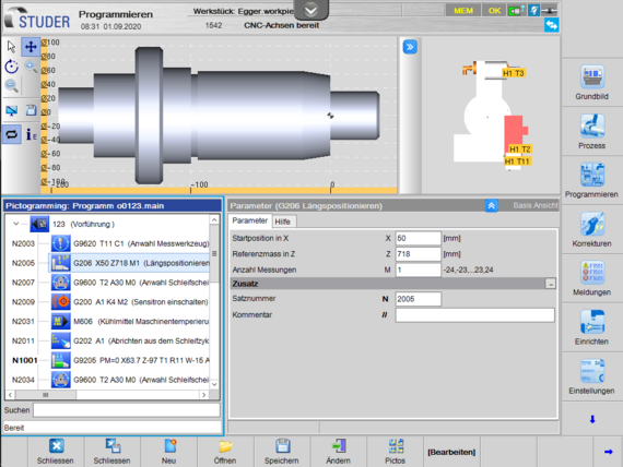
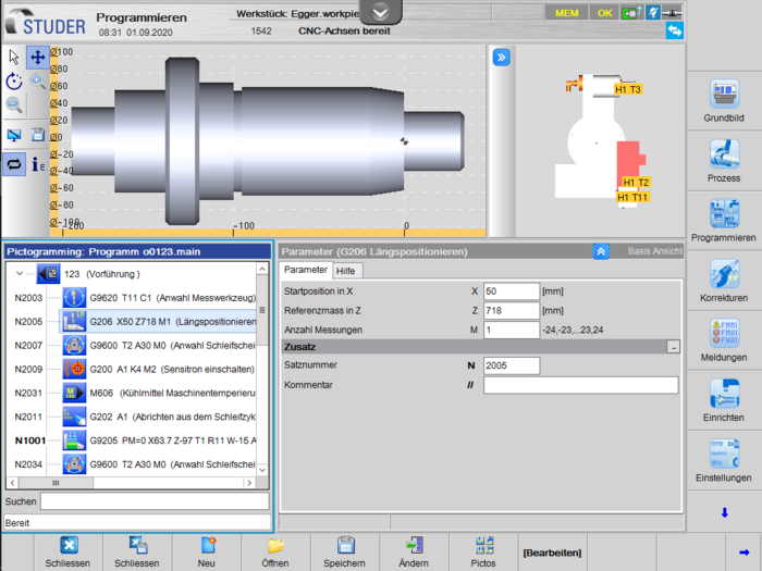
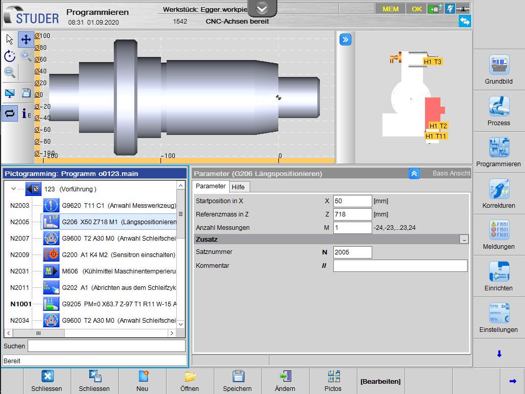
이제 공작물 프로그램에서 길이 방향 위치 지정 사이클에서 X 및 Z 값이 이에 따라 프로그래밍됩니다. 이 경우 프로브의 시작 위치는 X 50 및 Z에서 감지된 718mm입니다.


이후에는 임의의 다른 공작물로 전환할 수 있습니다. 이제 새로운 공작물 영점을 다시 감지하는 데 매우 적은 노력이 필요하다는 것을 알 수 있습니다. 이 공작물을 연삭하기 위해 다른 도구가 필요할 경우, 이후 이 도구를 추가로 기록해야 합니다.
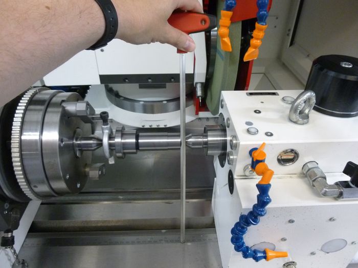

프로브 회전 위치를 다시 측정하십시오.

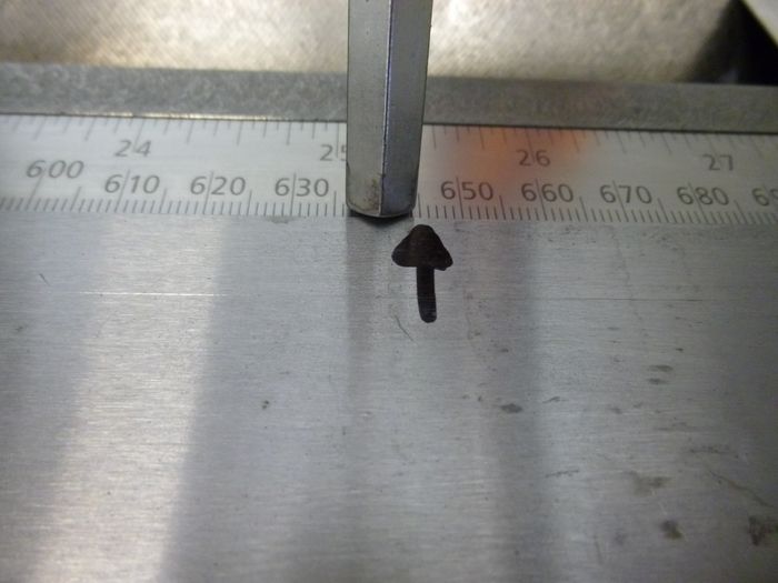

새로운 사례에서 테이블 스케일은 645mm를 나타냅니다.


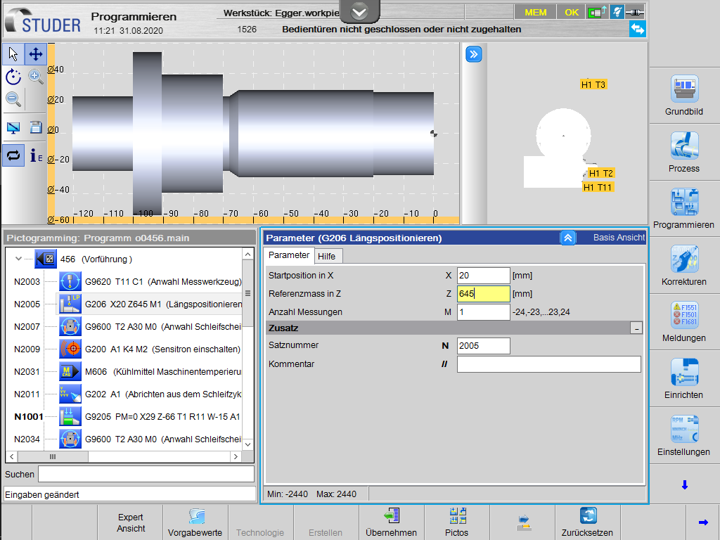
이 값은 새로운 공작물 프로그램의 길이 방향 위치 지정 사이클에서 다시 입력됩니다. X 20 및 Z 645mm.
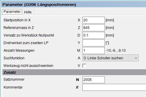
공작물의 연삭 여유 또는 기타 이유로 인해 Z 0이 정확하게 프로빙되지 않는 경우, 전문가용 보기에서 매개변수 D에서 해당 오프셋을 프로그래밍할 수 있습니다.


이제 새 프로그램이 시작되면, 기계가 프로브와 함께 해당 위치로 이동하고 그곳에서 새로운 영점이 설정됩니다.